
During the design of printed circuit boards (PCBs), a question that may always come to mind, although it is usually ignored seriously, is: will my design overheat? The management of heat is crucial to the life, stability, and efficiency of any given electronic gadget. Overheating may cause component failures, signal integrity problems and eventually, expensive redesigns or warranty. The ability to predict, prevent and control heat in your PCB design can spare you a great deal of pain in the future, no matter what your level of expertise is.
What Causes PCB Overheating?
The main cause of heat generation in PCBs is due to the presence of electrical current on traces, components, and connectors. Part of the electrical energy is transformed into heat by the resistance in copper traces. Potential overheating is caused by the high density of currents, ineffective thermal design and layout compactness, as well as insufficient cooling. Power transistors, voltage regulators, or processors dissipate much heat, which has to be effectively conducted.
This may lead to heat spots and damages on materials or on surrounding delicate components in case the thermal factors are not taken into account. Heat dissipation is also determined by PCB substrate material, copper thickness, and board layers. Hence, these factors are essential in controlling thermal reliability during the design.
Identifying Heat Risks in Your PCB.
Among the initial things that you should do to make sure that your PCB does not overheat is that you measure the amount of heat your traces or components should produce. These risks could be estimated using different tools.
A trace width calculator, such as the one provided by the use of the trace width calculator, will allow you to decide the optimal trace width to allow your given current to be safely carried without the temperature becoming too high. The high current traces are easily heated and thus it is important to make sure that you size the trace to your current needs and the temperature you are allowed to reach. These calculators take into account such influences as copper thickness, ambient temperature and tolerable temperature rises.
Equally, when you are designing with high-frequency signals, you can use an impedance calculator so that your traces are of the right impedance without generating signal reflections and attenuation which can also be a cause of unwanted heat.
Other than traces, any external wiring or connectors to the PCB must have its gauge of wire assessed. The correct thickness of a wire is a computation that is made with the help of a wire gauge calculator as an addition to the thermal control of your PCB.
Some Real Life Advice on preventing PCB overheating.
In addition to calculations, there are a number of useful design techniques which can enhance heat dissipation and can reduce thermal problems:
- Select the appropriate substrate, copper thickness. Copper layers of thickness above 2oz or more are used to dissipate heat better than the normal 1oz layers.
- Connect inner heat generating layers to outer components or ground planes using thermal vias which help in heat conduction.
- Spread the high-power components, instead of concentrating them in a single location and forming hotspots.
- Add thermal relief pads and copper pours as much as you can to dissipate heat off sensitive equipment.
- Plan your airflow design. Crowded component placement brings in heat and this should be avoided and also how your PCB will be enclosed, it may require heat sinks or fans to be added outside.
PCB prototyping services can also offer you choices of improved thermal performance or rapid iterations to test thermal performance prior to complete production in case you are simply prototyping your design.
The Role of Simulation and Testing
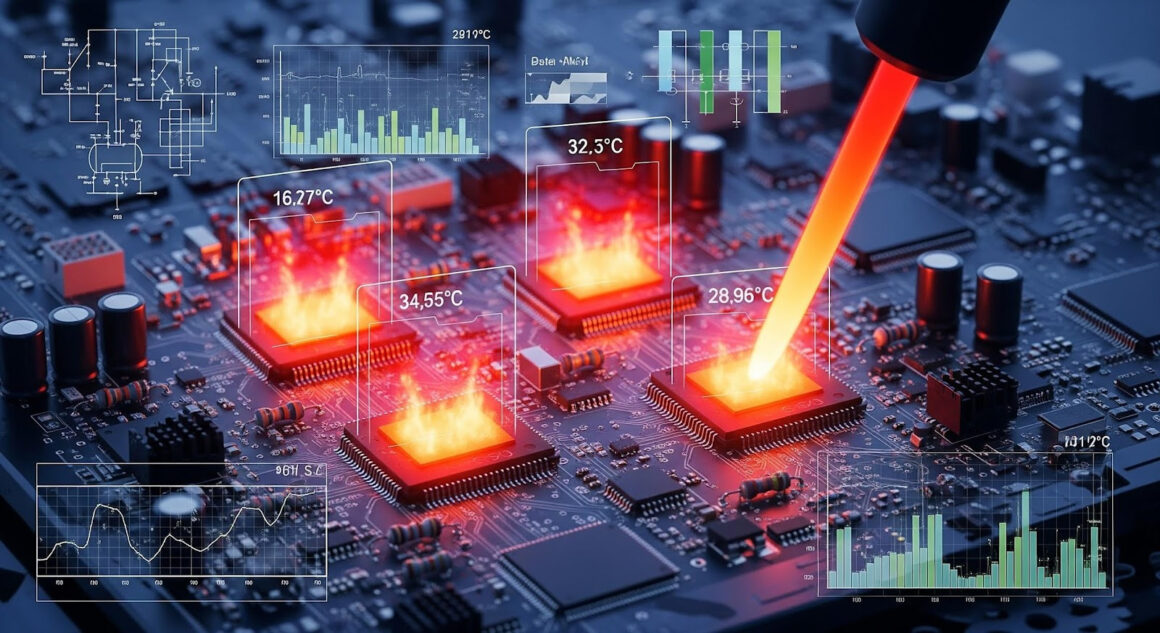
Simulators are able to forecast the thermal behavior without literally making an actual PCB. Heat generation and dissipation may be modelled with software and the risky areas may be found and would have to be redesigned. Thermal bottlenecks can also be identified by simulating airflow in your enclosure of your final product.
Once the prototype is assembled, thermal imaging test, or temperature sensor test is done to confirm your design works well in heat management. Before a mass production, you want to be sure that you have realistic figures.
Why Overheating Matters for Your Project’s Success
Disregard of thermal concerns may result in solder joint failures, delaminated areas, intermittent signal(s), or total component breakdown. PCBs are overheated making the product less reliable and less lifespan and therefore impacting customer satisfaction and brand image.
A good design that has adequate heat containment enhances stability, performance, and safety of the system. It also minimizes the troubleshooting of post production and expensive recalls. Given the added focus and low price incurred in the design of thermal management, it will be a payoff that is well rewarded in the success of the final product.
Final Thoughts: Take Control of Your PCB’s Thermal Health
To make sure that your PCB design does not overheat, you need to utilize both good theoretical knowledge and design methods and simulation. You can be sure of your layout and materials with the help of tools such as trace width calculators, impedance calculators and wire gauge calculators.
When embarking next project, it is important to keep in mind that thermal design is as important as signal integrity or mechanical fit. You should not be afraid to consult the experts when you are new to PCB design or challenging power electronics, but also when you are prototyping a new PCB, it does not hurt to use PCB prototyping services to test your thermal intentions.